INDUCTANCE AND CAPACITANCE OF TRANSMISSION LINE
AIM:
To find inductance and capacitance of transmission line for various conductor arrangements, using MATLAB.
THEORY:
A single phase line consists of two parallel conductors which from a rectangular loop of one turn. When an alternating current flows through such a loop, a changing magnetic flux is setup. This changing flux links the loop and hence the loop (or single phase line) possesses inductance. It may appear that inductance of a single phase line is negligible because it consist of a loop of one turn and the flux path is through air of high reluctance. But as the cross-sectional area of the loop is very large even for a small flux density, the total flux linking the loop is quite large and hence the line has appreciable inductance.
Let A, B &C of a three phase line carrying currents Ia, Ib&Ic respectively. Let d1, d2&d3 be the spacing between the conductors. At balanced condition Ia+Ib+Ic=0.There will be flux linkage with one conductor due to its own current and also due to the mutual inductance effects of other conductors. Here two cases arise symmetrical and unsymmetrical spacing.
Electric potential is important factor for the determination of capacitance in a circuit because capacitance is defined as charge per unit potential. The electric potential at a point due to a charge is the work done in bringing a unit positive charge from infinity to that point.
In three phase transmission line the capacitance of each conductor to ground is considered instead of capacitance from conductor to conductor. Here two cases arise symmetrical and unsymmetrical spacing.
PROBLEM:
A single phase transmission line has two parallel conductors 3m apart. The radius of each conductor is 1cm.Calculate the loop inductance per km of length of the line. Find the capacitance with epsilon ε = 8.854*10-12 and frequency = 50 Hz
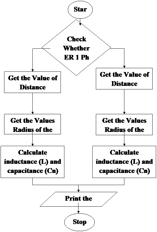
FLOW CHART:
PROGRAM:
disp('Single phase line');
disp('Three phase line');
choice=input('Enter your choice');
k=input('Epsolan');
res=input('Resistance');
r=input('Radius');
f=input('frquency');
switch choice
case 1
d=input('Distance');
l=(1+(4*log(d/r)))/(10);
c=2*pi*k*(10)/log(d/r);
case 2
d12=input('d12');
d23=input('d23');
d31=input('d31');
deq=(d12*d23*d31)^(1/3);
l=(0.5+(2*log(deq/r)))/10;
c=(2*pi*k/log(deq/r))*(10);
end
xl=2*pi*f*l;
xc=1/(2*pi*f*c);
z=complex(res,xl);
y=complex(0,xc);
disp('Inductance in mH/Km');
disp(l);
disp('capacitance in micro farad per Km');
disp(c);
disp('z=');
disp(z);
disp('y=');
disp(y);
OUTPUT:
SINGLE PHASE LINE
Single phase line
Three phase line
Enter your choice =1
Epsilon = 8.854*10^-12
Resistance = 0
Radius =1
Frequency =50
Distance =300
Inductance in mH/Km = 2.3815e-006
Capacitance in micro farad per Km = 0.0098
Z =0 +7.4817e-004i Ω
Y =0 + 0.3264i mho
THREE PHASE LINE
Single phase line
Three phase line
Enter your choice =2
Epsilon=8.854*10^-12
Resistance =0
Radius =1
frequency =50
d12 =300
d23 =300
d31 =300
Inductance in mH/Km=1.1908
Capacitance in micro farad per Km= 0.0098
z=0 +3.7409e+002i Ω
y=0 + 0.3264i mho
RESULT:
Thus the program for calculating capacitance and inductance of transmission line was written and output obtained using MATLAB.