Automatic Incubator Full Set
Low
cost 32 EGGS incubator
RS
8500 only
Calibrated with standard
thermometers
Accurate Upto 0.5
Degree C
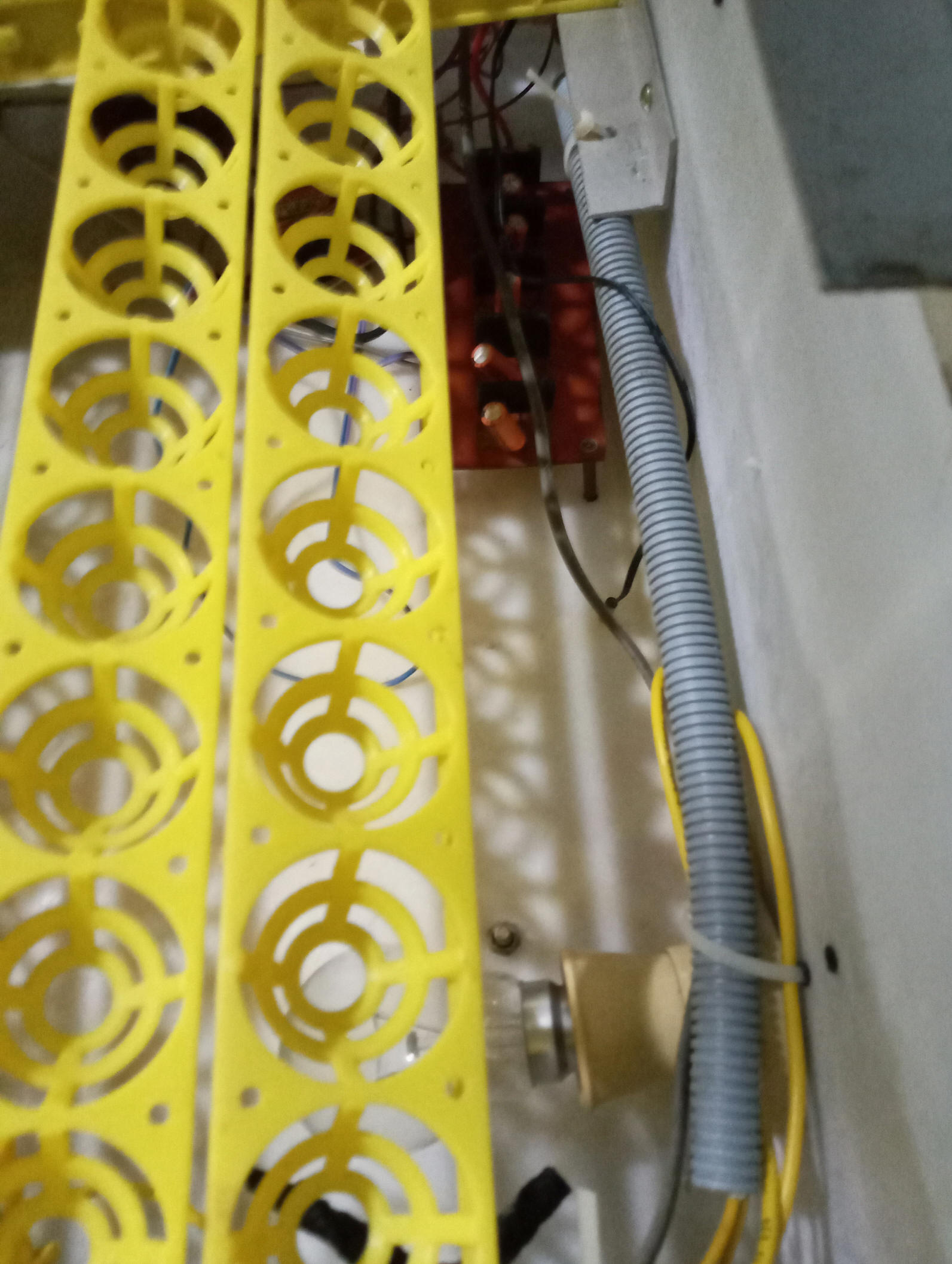
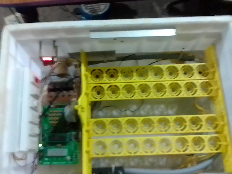
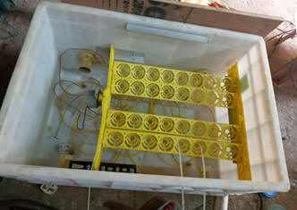
Our 5B Model incubator is full
automatic works with By the two-cycle system Double-circulation: two
sets humidifying and heating system to make sure of normal work.
Full automatically eggs
turning, Full automatically alarming,
Our incubator is very energy-saving.
All of the parts of our incubators are energy-saving and high
quality.
Full unit tested strictly by our
engineer and when it passed the test to market.
Each of our incubator has free parts
of electrical machine of egg turning, egg candler, heat pipe,
humidity pipe etc. free to give you. Warranty 1 years.
It can keeping temperature very well.
All of our accessories are high
quality.
Features:
1. Mirco-computer controlled on
temperture &humidity 2. Energy can be electricity
3. Automatic egg turning, automatic
alarm on temperature&humidity
4. Energy-saving and environment
protection
5. The incubator combines the setter
and hatcher together in one.
For sales and support / spares /
Customer support at +91-8608603634
POINTS
TO NOTE
The
best way to test if an egg is "good" (fertile) or not is to use a
technique called "candling". This technique gets it's name from the
way it was done before electric light bulbs. A person would use a
candle to create enough light to try to see what is happening inside
an egg. With electric light bulbs, this has become easier and more
reliable. Candling
system can help to determine if the chick is developing according to
expectations. During candling, if detected the dead embryos, it need
to remove from Smart Egg Incubator. If the egg was not removed, it
will produce unwanted gas. Candling system starts on the 9th day of
incubation.
Eggs from stores will not hatch.
no incubator produces 100% hatching.
Our test reports on incubator
The normal incubation time of most
chickens is 21 days or 21 days, 6 hours. Temperature is probably the
most important single factor influencing the development of the
embryo. Near the optimum incubation temperature ranges, a higher
temperature will advance the hatch and a lower temperature will
delay hatch. A one-half-degree change in average incubation
temperature will move the average hatch time by about 5.4 hours.
To monitor the temperature, place a calibrated and accurate
thermometer 1 inch above the wire mesh screen on which the eggs sit.
This location corresponds approximately to the top of the eggs,
where the temperature should be measured.
Temperature too high. Wenger embryos are especially susceptible to
high temperatures because the upper lethal limit is very close to
the optimum incubating temperature. Operating the incubator at 105
degrees Fahrenheit for 30 minutes will seriously affect, if not
kill, the embryos. High temperature will lead to nervous problems,
heart and circulatory problems, and kidney problems and will cause
the embryonic membranes to dry out too soon. Chicks that hatch may
have clubbed, wiry down and an unsteady gait.
Factors that were considered during
the performance evaluation of the incubator were humidity, 55% and
temperature, 37 degree C during the first 18 days and was maintained
at 37.5 degree C till hatching. Turning of eggs was achieved with
the use of tilting trays mechanism using an electric low rpm motor.
The trays were lifted through an angle of 40 degree on either side
of horizontal at every hour and lasted for 0.5 minutes and
hatchability of 84.06% was obtained during testing.
Approximately three to four days before hatching is a good time to
remove eggs that appear to be infertile or contain dead embryos.
Check the eggs by candling, and handle the nonhatching eggs
carefully.
It may be helpful to place several layers of cheesecloth over the
wire mesh on the bottom of the incubator four days before hatch.
This provides a smooth surface to help keep the chicks from injuring
their navels or getting their legs caught in the mesh. This also
helps keep the incubator clean and the shells out of the water pan.
The hatching process releases much fluffy debris inside the
incubator. Care should be taken not to open the incubator in drafts
and to carefully remove shells and debris. Wearing gloves and a face
mask may help to provide better hygiene while doing this clean up.
Birds Incubation period
Pigeon 18 days
Pea fowl 28 days
Chicken 21 days
Turkey 28 days
Pheasant 21 to 24 days
Goose 28 to 32 days
Guinea 26 to 28 days
Muscovy duck 35 to 37 days
Duck 28 days
Ostrich 42 days
Proper humidity is important because it keeps the egg from losing
too much or too little moisture during the incubation process. Eggs
should lose between 11 and 14 percent of their weight from day 1 to
day 18 of incubation. This weight loss is a direct indicator of
humidity control.
Humidity should be balanced with temperature; different temperatures
require different relative humidities. Relative humidity should be
60 to 65 percent for the first 18 days of incubation, and 70 percent
for the last three days. The water pan in the incubator should be
kept full at all times. Use warm water to fill the pan. Humidity
adjustments are made as discussed above in the calibration section.
Opening the incubator to turn the eggs will cause a loss of
humidity. In very dry environmental conditions, sprinkle the eggs
with a little warm water after turning them. We can determine the
rate of dehydration by using a flashlight or slide projector to
candle, or shine through, an egg so that we can examine the
contents. If the air cell is too large, the humidity must be
increased. Low humidity can cause the chick to stick to the shell
and membranes at hatching. If the air cell is too small, the
humidity must be decreased. Excessive humidity will weaken the chick
to the point that it can't emerge from the shell at hatching.
From day 19 on, condensation on top of the incubator indicates
adequate humidity is present. The amount of condensation varies
depending on the temperature of the room where the incubator is
located.
It is best not to open or move the incubator during the last three
days of incubation for more time than it takes to add water to the
pan.
Temperature Controller
The W1209 is an incredibly low cost yet highly functional thermostat
controller. With this module we can intelligently control power to
most types of electrical device based on the temperature sensed by
the included high accuracy NTC temperature sensor. Although this
module has an embedded microcontroller no programming knowledge is
required.

3 tactile switches allow for configuring various parameters
including on & off trigger temperatures. The on board relay can
switch up to a maximum of 240V AC at 5A or 14V DC at 10A. The
current temperature is displayed in degrees Centigrade via its 3
digit seven segment display and the current relay state by an on
board LED.
SPECIFICATION:
Temperature Control Range: -50 ~ 110 C
Resolution at -9.9 to 99.9: 0.1 C
Resolution at all other temperatures: 1 C
Measurement Accuracy: 0.1 C
Control Accuracy: 0.1 C
Refresh Rate: 0.5 Seconds
Input Power (DC): 12V
Measuring Inputs: NTC (10K 0.5%)
Waterproof Sensor: 0.5M
Output: 1 Channel Relay Output, Capacity: 10A
The unit Power Consumption
Static Current: <=500mA
Under Lamp on Current: <=2A
Environmental Requirements
Temperature: -10 ~ 60 C
Humidity: 20-85%
Settings Chart
Long press the “SET” button to activate the menu.
Code Description Range Default Value
P0 Heat C/H C
P1 Backlash Set 0.1-15 2
P2 Upper Limit 110 110
P3 Lower Limit -50 -50
P4 Correction -7.0 ~ 7.0 0
P5 Delay Start Time 0-10 mins 0
P6 High Temperature Alarm 0-110 OFF
Long pressing +- will reset all values to their default
Displaying the current temperature:
The thermostat will display the current temperature in oC by
default. When in any other mode making no input for approximately 5
seconds will cause the thermostat to return to this default display.
Setting the trigger temperature:
To set the trigger temperature press the button marked 'SET'. The
seven-segment display will flash.
We can now set a trigger temperature (in oC) using the '+' and '-'
buttons in 0.1-degree increments. If no buttons are pressed for
approximately 2 seconds the trigger temperature will be stored and
the display will return back to the current temperature.
Setting the parameters:
To set any parameter first long press the 'SET' button for at least
5 seconds. The seven-segment display should now display 'P0'. This
represents parameter P0. Pressing the '+' or '-' buttons will cycle
though the various parameters (P0 to P6). Pressing the 'SET' button
whilst any of there parameters are displayed will allow we to change
the value for that parameter using the '+' and '-' buttons (see
below). When finished setting a parameter press the set button to
exit that option. If no buttons are pressed for approximately 5
seconds the thermostat will exit the parameter options and will
return back to the default temperature display.
Setting the cooling or heating parameter P0:
The parameter P0 has two settings, C and H. When set to C (default)
the relay will energise when the temperature is reached. Use this
setting if connecting to an air-conditioning system. When set to H
the relay will de-energise when the temperature is reached. Use this
setting if controlling a heating
device.
Setting the hysteresis parameter P1:
This sets how much change in temperature must occur before the relay
will change state. For example, if set to the default 2oC and the
trigger temperature has been set to 25oC, it will not deenergise
until the temperature falls back below 23oC. Setting this hysteresis
helps stop the thermostat from continually triggering when the
temperature drifts around the trip temperature.
Setting the upper limit of the thermostat parameter P2:
This parameter limits the maximum trigger temperature that can be
set. It can be used as a safety to
stop an excessively high trigger temperature from accidentally being
set by the user.
Setting the lower limit of the thermostat parameter P3:
This parameter limits the minimum trigger temperature that can be
set. It can be used as a safety to stop an excessively low trigger
temperature from accidentally being set by the user.
Setting temperature offset correction parameter P4:
Should we find there is a difference between the displayed
temperature and the actual temperature (for instance if the
temperature probe is on a long run of cable) we can make minor
corrections to the temperature reading with this parameter.
Setting the trigger delay parameter P5:
This parameter allows for delaying switching of the relay when the
trigger temperature has be reached. The parameter can be set in one
minute increments up to a maximum of 10 minutes.
Setting the high temperature alarm parameter P6:
Setting a value for this parameter will cause the relay to switch
off when the temperature reaches this setting. The seven-segment
display will also show '---' to indicate an alarm condition. The
relay will not re-energise until the temperature falls below this
value. The default setting is OFF.
Embedded Systems Design and
Development
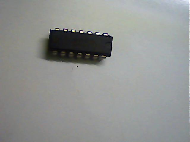
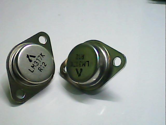
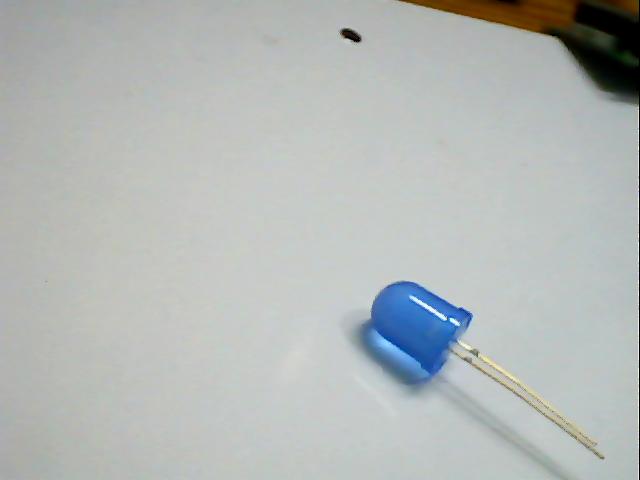
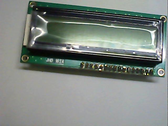
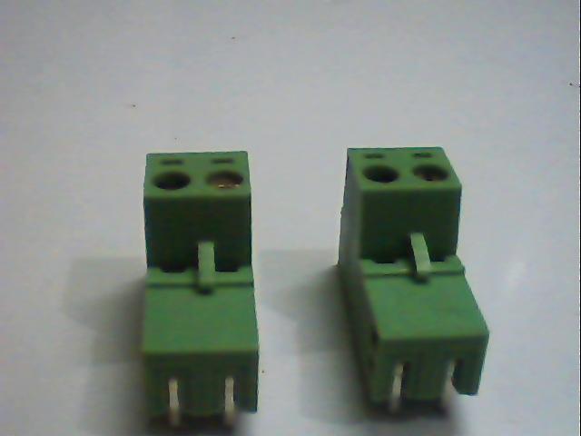
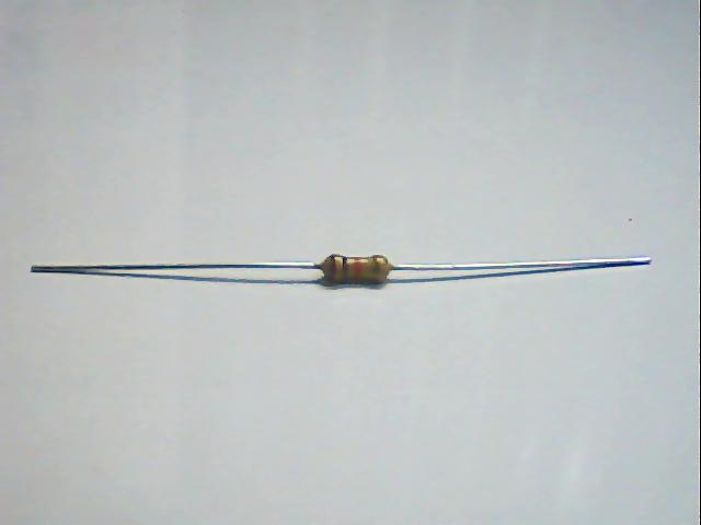
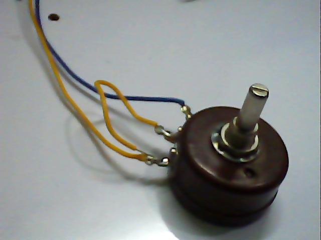
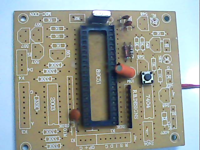
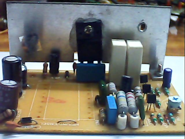
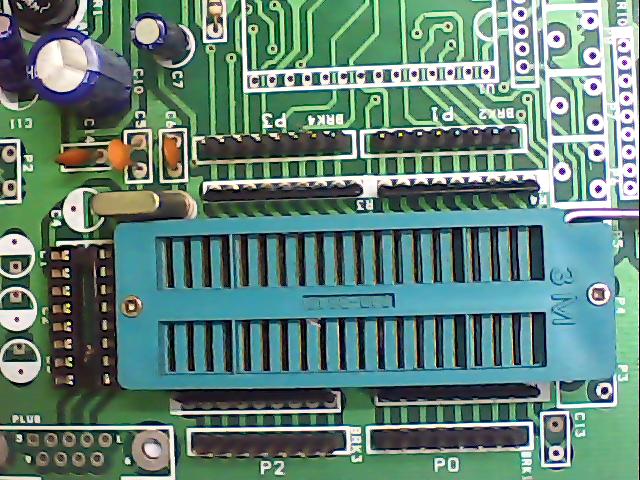
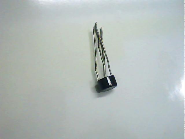
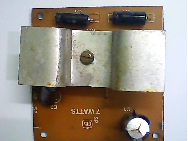
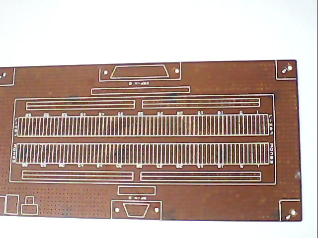
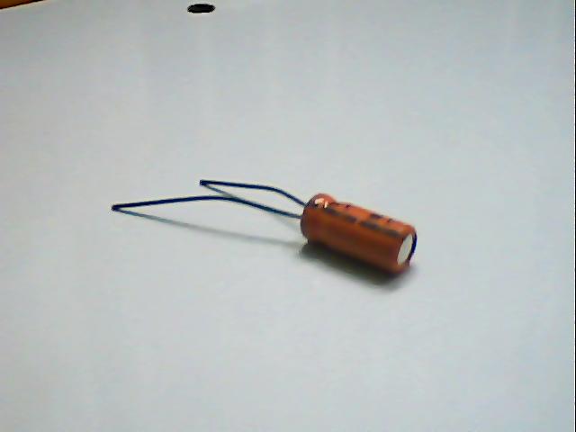
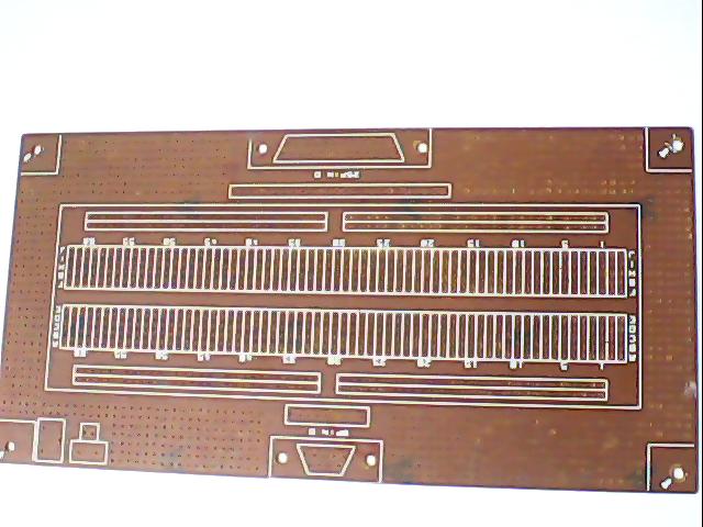
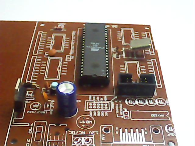
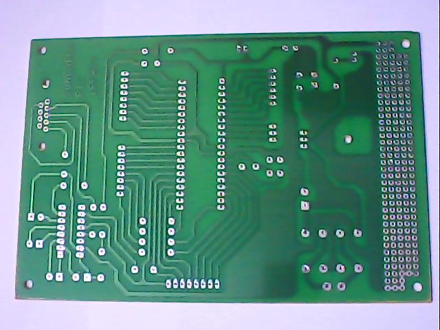
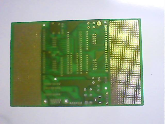
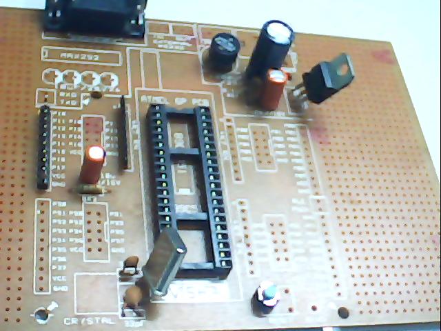
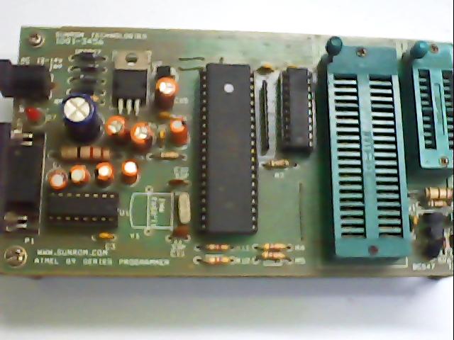
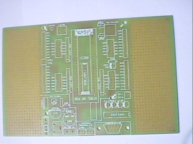
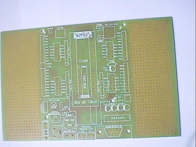
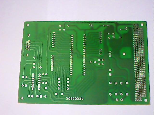
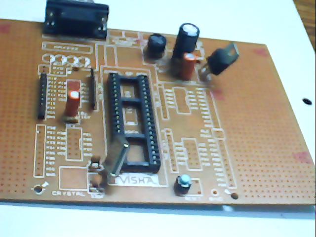
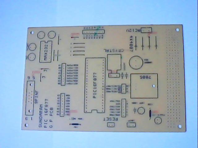
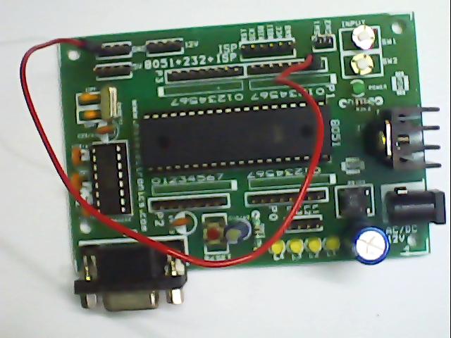
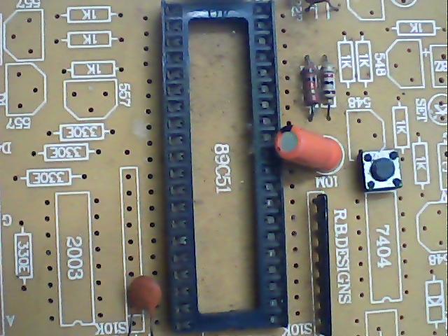
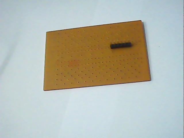
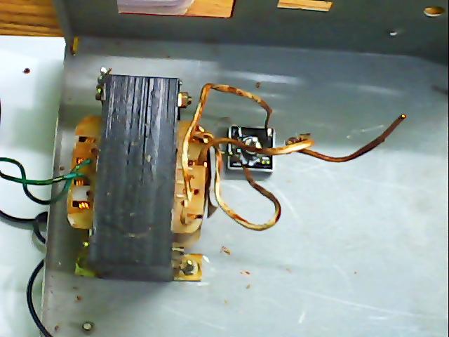
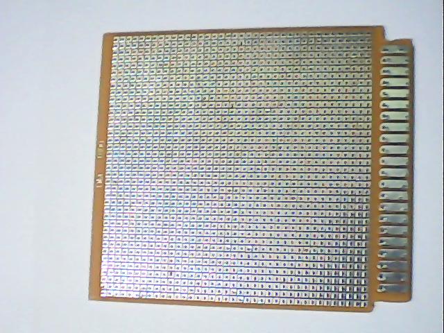
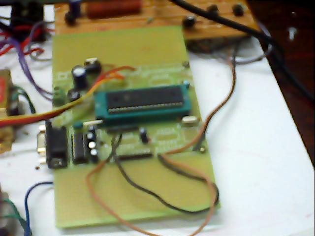
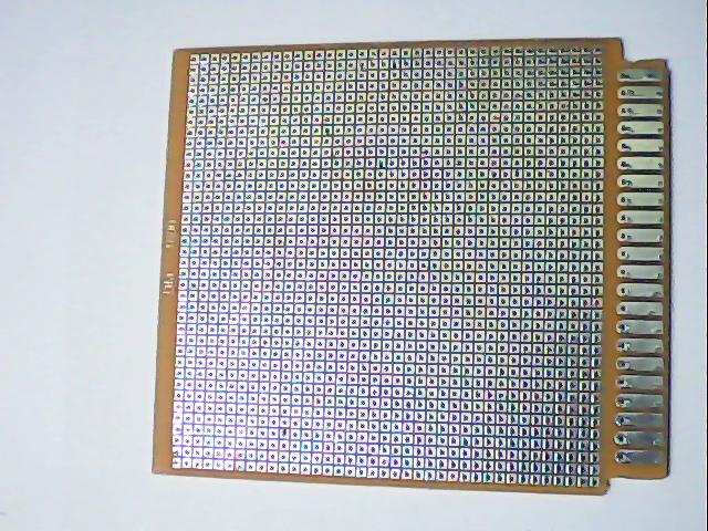
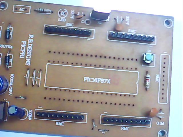
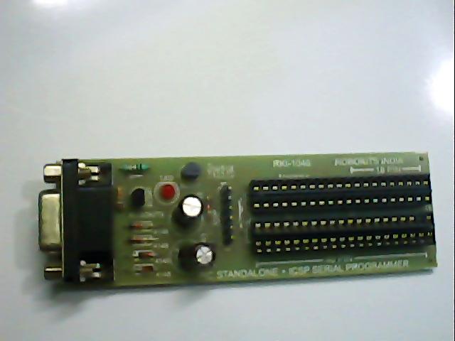
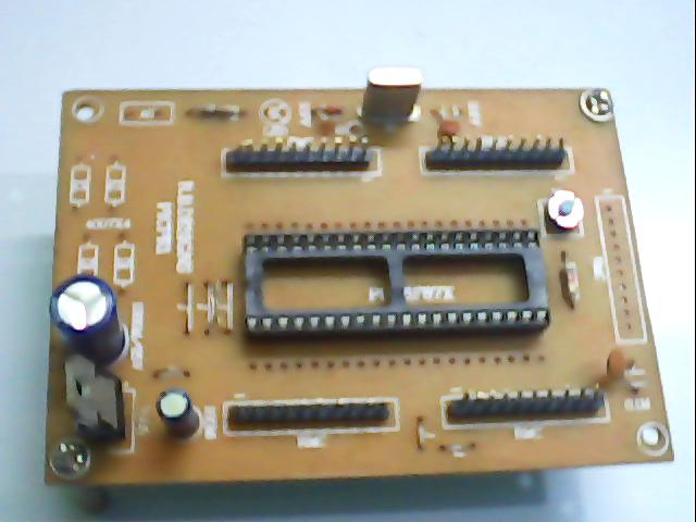
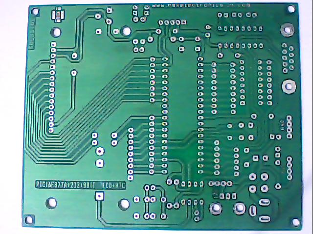
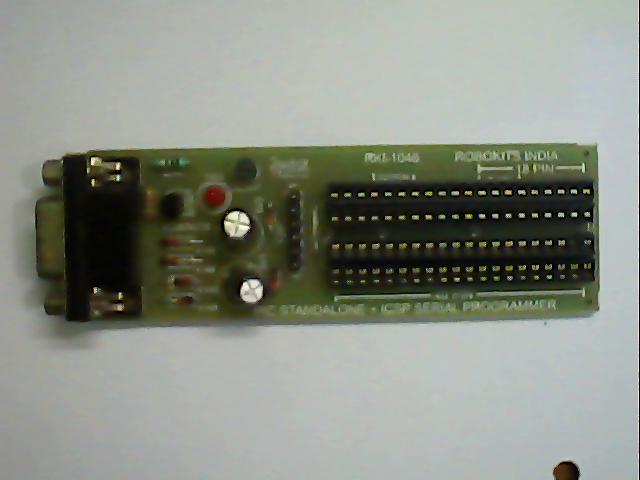
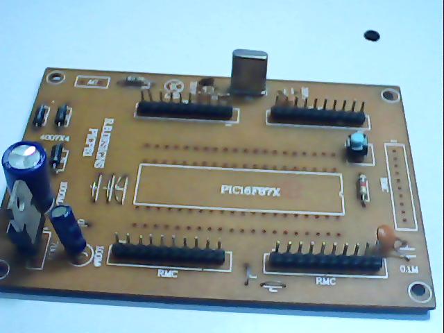
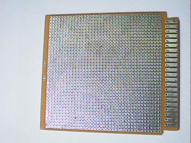
The below mentioned
Products are needed for development of embedded applications. our Wide
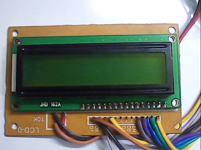
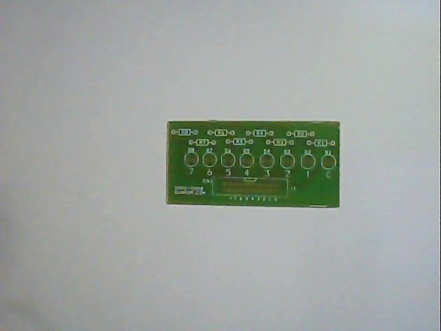
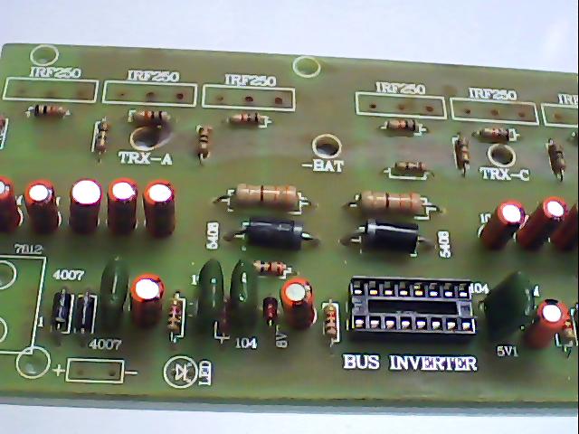
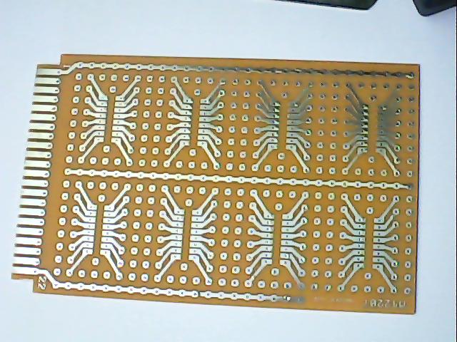
spectrum of embedded products in sale are listed below.
|
|
PRODUCT IMAGE |
INFORMATION |
|
|
 |
|
|
|
 |
|
|
|
 |
|
|
|
 |
|
|
|
 |
|
|
|
 |
|
|
|
 |
|
|
|
 |
|
|
|
 |
|
|
|
|
|
|
|
  |
|
|
|
 |
|
|
|
 |
|
|
|
 |
|
|
|
 |
|
|
|
 |
|
|
|
|
|
|
|
 |
|
|
|
|
|
|
|
 |
|
|
|
 |
|
|
|
 |
|
|
|
 |
|
|
|
 |
|
|
|
 |
|
|
|
 |
|
|
|
 |
|
|
|
 |
|
|
|
 |
|
|
|
 |
|
|
|
 |
|
|
|
 |
|
|
|
 |
|
|
|
 |
|
|
|
 |
|
|
|
 |
|
|
|
 |
|
|
|
 |
|
|
|
 |
|
|
|
 |
|
|
|
 |
|
|
|
 |
|
|
|
|
|
|
|
 |
|
|
|
 |
|
|
|
 |
|
|
|
 |
|
|
|
 |
|
|
|
 |
|
|
|
 |
|
|
|
 |
|
|
|
 |
|
|
|
|
|
|
|
 |
|
|
|
 |
|
|
|
 |
|
|
|
 |
|
|
|
 |
|
|
|
 |
|
|
|
 |
|
|
|
 |
|
|
|
 |
|
|
|
 |
|
|
|
 |
|
|
|
 |
|
|
|
 |
|
|
|
 |
|
|
|
 |
|
|
|
 |
|
|
|
 |
|
|
|
 |
|
|
|
 |
|
|
|
 |
|
|
|
 |
|
|
|
 |
|
|
|
 |
|
|
|
 |
|
|
|
 |
|
|
|
 |
|
|
|
 |
|
|
|
 |
|
|
|
 |
|
|
|
 |
|
|
|
 |
|
|
|
 |
|
|
|
 |
|
|
|
  |
|
|
|
 |
|
|
|
 |
|
|
|
 |
|
|
|
 Email:
